


GPS SPEEDOMETER
I am building a speedometer for
my lakester that I hope will give me reasonably accurate
speed data during a run at Bonneville. In the past, I have
tried to read the tachometer as I pass through the last
mile marker to get some idea of my speed. Between the car
vibrating, the wind buffeting my helmet, and the general
anxiety of keeping the car straight at speed, I have been
pretty unsuccessful. Oh, I could say it was doing maybe
7700 rpm, but it could have been almost anywhere betwen
7500 and 8000. It was just a guess.
By a process of absolute serendipity, I ended up with a
small computer card with embedded BASIC and lots of I/O
options that just begged to be put to some practical use.
Web searches uncovered a GPS module that offers a speed
output and a display card with large, bright LED's. Put
them together and I just might have something that I can
actually see at speed.
The computer card -- really, it's more like a 40-pin DIP
chip -- is from EZsbc. The one I got is the EZsbc1.
Uses an LPC2138 ARM-7 processor from NXP. It has a
version of BASIC installed as the O/S. Programming it
requires a PC running a terminal program (I used
HyperTerm) and a USB port with a driver program. There
is a download page on their website that explains how to
do this and it is simpler than it appears (especially if
you use HyperTerm and ignore all the setup info on
TerraTerm). It should be possible to program this card
from a Mac, as well. I hope to try this one of these
days.
This card/chip has a lot of I/O pins, including a dedicated
SPI bus, TTL-level serial bus, I2C bus, and several ADC
inputs. A number of the pins can be used as PWM outputs,
which seems to be quite the thing among the robot crowd for
driving small motors.
My first display was a 4-digit 1.2" LED module mounted on a
backpack card with the driver chip and an I2C I/O. This
card is produced by Adafruit as well but I bought mine
from InterTex Electronics in San Antonio. This rascal
proved to be rather difficult to interface to the EZsbc.
Hard to decide who to blame...so I won't bother. But
here's what happened.
Adafruit supplies C libraries for any of their products
that are intended to be interfaced to a computer. The
libraries are specific to the Arduino and the Raspberry Pi
computer cards. They offer comprehensive instructions for
assembling any cards that are kits and for hooking them up
and running sample code. If, however, you are going to use
something other than one of these computer cards to drive
their cards, you are pretty much left to figure things out
on your own.
In the case of the LED display, I managed eventually to
find enough examples of driver code and explanations of how
various folks got this card to work, that I came up with a
general idea of how to manage this chip. The chip powers up
in Standby mode, which means the LED's are all off. To
start the chip driving the LED segments, you have to send
it three commands via the I2C bus. Each command must be
preceded by the card address -- which is 0xe0, no matter
what Adafruit says in their instructions. (Yes, the chip
'address' is 0x70 but this is a 7-bit address and to get
the chip to actually write the address internally so that
the following command is processed, you have to left-shift
the address and add a zero to form an 8-bit value, which
happens to be 0xe0.) Thus, a triplet of 2-byte commands
must be sent to the card. I sent them in this order (the 0x
prefix stuff is IBM's way of writing hexadecimal
characters; you don't actually send those characters):
0xe0 0x21 (enables the on-board oscillator)
0xe0 0xef (sets the brightness to max
0xe0 0x81 (sets the display to ON
It took me several days to get this right. Not that the
commands were hard to figure out (everyone mentioned these)
but because I hard-headedly refused to believe the scope
display of the data on the I2C line. I was using the EZsbc
BASIC command
I2CWR(slave address, register to write, data string, number
of bytes)
to send the commands. In particular, I would program
c$=chr$(0x21)
i2cwr(0xe0,0,c$,1)
which, it turns out, sends the bytes 0xe0, 0x00, and 0x21
to the card. When I finally realized that I was sending
THREE bytes to the display chip, I changed the code to try
c$="x"
i2cwr(0xe0,0x21,c$,0)
and everything began working. The rest was pretty simple. I
wrote some test code (see the downloads page) that lets me
enter a number, parses out the digits, and displays them on
the LEDs. The only 'trick' to this code is realizing that
1) you have to send the segment codes rather than the
numbers to the chip and 2) the digits are located at
addresses 0, 2, 6, and 8. The colons and decimal points are
at address 4. The code listing should be self-explanatory.
If you can't read BASIC then you're probably a C-programmer
and Adafruit has you covered already. I was disappointed at
the brightness of this large display so I ordered a .56"
display and backpack to try. The Adafruit folks have their
stuff together -- it was a simple unplug/replug to install
the new display. No code changes, the wires are in the same
order. Easy. Oh, and it is brighter, which will be
important in the sunlight on the salt.
I ended up ordering The Ultimate GPS breakout from Adafruit.
This module has a GPS on a chip, with provision for
using either the antenna on the chip or an external
antenna, and a simple ASCII interface using TTL-level
serial I/O. The GPS module is a pretty simple
plug-and-play device. It requires 5V power and
communicates via a TTL-level serial bus. Four wires and
some code. Pretty easy. I got the code mostly working
with the modules on a powered breadboard but it was
quite a pain to lug everything outside and setup a table
to see the GPS get a fix (my shop is in a metal hangar).
Besides, I wanted to see it work when I was driving. So
I constructed a simple breadboard circuit with
everything plugged in, using a 7805CT fixed 5V regulator
to power everything. I had a 12V small battery around
for a power source (you could use the power port on most
modern cars, too).
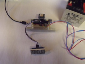

The EZsbc card can be powered through the USB port, which
is ideal for developing code. My laptop provides enough
current to run the whole thing (about 90 mA with the
smaller display shown). On battery power, I provide 5V to
the EZsbc card from the regulator but I don't hook up the
USB and battery power at the same time. Check out the
schematic for the EZsbc1 to see why -- there is a small 2.2
ohm resistor between the 5V input on the USB connector and
the 5V pin on the card itself. If the voltages differed by
much, you could blow this resistor or possibly hurt the USB
port driver in your computer.
The Speedometer schematic is available on the download
page. Basically, there are four wires and power. Simple.
Does it work? Yep! Works fine. I send some commands to the
GPS module to increase the update rate of the VTG message
(the one that contains speed over the ground) and slow the
rate of the RMG message (which I only use to determine that
the chip has found some satellites and has a position fix).
I hope this will let the speed display keep up with the
accelerating car (as of this moment, however, the update
rate has not taken effect; hmmm). As we enter the last mile
on the five mile course, however, the rate of change of
speed is not so fast and I suspect even the base setting
(once per second) would keep up with speed changes. I have
written a version of this code that keeps track of the
maximum speed. This might be what I really want to display,
although I would love to know just how fast I'm going when
I turn off the course too. So I may add a toggle switch or
a button to display the max speed after I come to a stop.
Easy -- it's just code now.
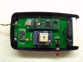
Total parts cost -- under $100. Just for fun, I laid out a
printed circuit to fit a box I found at InterTex
Electronics. Here is the result:

I've tried it out at the Texas
Mile and at El Mirage. Had an issue with saving the max
speed at El Mirage that I haven't sorted out yet, however.