


TRANSDUCER
DESIGN
This is where I plan to put the data I have accumulated on
transducer construction. I recently wrote a preliminary
report on building TAPS transducers. The first draft of
this report is on the downloads page. It contains the
information below plus some hints on testing, tuning, and
calibrating TAPS transducers. Feedback would be
appreciated.
Ok, I did put a document on the DOWNLOADS page that
discusses the optimum thickness of backing materials on the
TAPS transducers. This won't make much sense without some
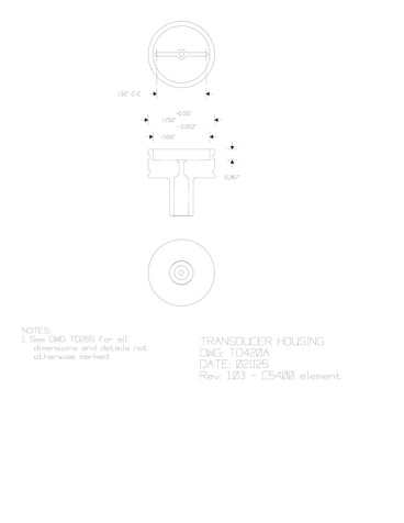
notion of how the transducers are made. Briefly, the TAPS
transducers are made from circular disk elements with
electrodes on the large faces. They are assembled into
housings like the drawing below. A thin piece of Copaco --
a tradename for a paper insulator used in electrical motors
-- is glued to the back side of the element using
Scotchcast 1838 structural adhesive and this assembly is
then glued into the housing. The cavity is then filled with
epoxy to waterproof the assembly and to provide a matching
layer from the ceramic to water.
I begin by soldering a wire to the back electrode at the
center. I prefer to attach the wire standing straight up
from the electrode; the wire is tinned and then soldered to
the electrode. This joint is tested for strength (gently),
then cleaned with MEK and a small dab of 5-minute epoxy is
applied to give the joint some mechanical strength.
When cured, the back is spread with a thin layer of
adhesive, the copaco backing (with a hole in the center) is
threaded over the wire, and another layer of adhesive
applied to the other side of the copaco.
A second wire is threaded through the hole in the housing
and along one of the machined channels in the transducer
cavity, lapping over the side of the housing. Structural
adhesive is applied to fill these channels and then the
transducer assembly (element and copaco) is inserted with
the attached wire fed through the hole with the other wire.
The element is rotated and pressed downward to create a
uniform thin layer of adhesive under the copaco. Extra
adhesive that is extruded can be removed with a Q-tip.
I cure these assemblies overnight with a small weight
pressing on the ceramic to ensure a thin joint. Use some
sort of non-abrasive material between the ceramic and the
weight to prevent damaging the upper electrode.
Next day, I inspect the transducer and then attach the
second wire to the face electrode. I usually tin the wire
and then flatten it with needlenose pliers before I solder
it to the ceramic. Then I hook up the wires to an
oscilloscope and thump the ceramic with the eraser end of a
pencil. You should see 100-200 mV peaks on the response.
The cavity is then filled with epoxy resin and left to cure
(again, overnight).
Day three has me attaching wires -- often RG-74 coax -- to
the two wires coming out the back of the housing. I try to
make a tidy joint that I can push into the housing and then
seal with more epoxy resin.