


SINGLE BOARD COMPUTERS
AND FORTH
I have used a couple of single
board computers (SBC's) from New Micros Inc. in Dallas, TX
as controllers for oceanographic sensors. The particular
boards I've used are the 68HC11 and 68HC12 cards, along
with a few accessory cards. Schematics of controllers using
these cards can be found in the TAPS-6 and TAPS-8 sections
on this site.
The 68HC11 card came with FORTH embedded in the ROM on the
cpu chip. A later variant added floating point to the ROM
and I exchanged this CPU for all the previous ones to get
this feature. I had actually heard of FORTH before I got my
hands on one of these SBC's. A friend in Oregon had told me
casually, one day, that he had written some code in FORTH
and that it was very strange stuff indeed. Used things like
commas as commands. Strange indeed. But I needed a very low
power CPU card to run some sensors I was building for a
mooring that would have to run on batteries for long
periods unattended. And this SBC had the least current draw
of any that I found. So ... I had to learn FORTH.
I bought the book by Leo Brodie, "STARTING FORTH"
(available on-line at FORTH, INC) and started
learning. With the 68HC11 SBC, the card became the
language lab. Hooked it up to a PC running a serial
terminal program (BitCom for the 80386 cpu -- still use
it today!) and applied power. The card sent a startup
message line and was now ready for me to program.
FORTH is a peculiar sort of O/S, reminiscent of the BASIC
O/S that came on the early Apple computers. It consists of
defined WORDS which you can call directly from the command
line. You can also define new WORDS using the old WORDS and
any new WORDS you have previously defined. Typing the name
of any of these WORDS will cause that WORD to be executed.
If you think SUBROUTINE for WORD, then this isn't all that
strange. Generally, one builds a program by defining WORDS
that do specific things -- collect data from an ADC,
generate ping gates on a digital line, convert a number to
dB, etc. Each word can be tested by itself until it is
working properly. When the whole program is done, there
will be a last WORD (I always call mine MAIN) that starts
the whole thing going.
Another peculiarity of FORTH is the use of stacks to hold
data. WORDS exchange data using the stack. If a WORD
requires some input data, the typical way to provide it is
to put the data on the stack before calling the WORD. Being
FORTH, this is done as schematically as possible: if the
data were held in locations called, say, DATA1 and DATA2,
and the WORD that needed the data was called PROCESS, then
the calling sequence would look like
DATA1 @
DATA2 @
PROCESS
In other words, naming a data variable and calling the WORD
"@" (fetch) puts the data on the stack and naming (typing)
the WORD "PROCESS" evokes this code. The answer will, in
all likelihood, also be placed on the stack.
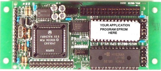
On the 68HC11 board, I tested the program by loading it
into RAM in the upper 32K of the 64K memory map. The SBC
had a socket for a memory IC. When I was happy with the
program, I would make a Motorola S-file image of the
program (by running a program supplied by NMI) and save it
in a capture file on the PC. I used this file to burn an
EPROM which I installed in place of the RAM chip and there
was an operating sensor controller. (There are some details
left out here, such as autostarting the code. But since the
supplier has closed shop, the details are now moot). The
picture below is one of the 68HC11 cards offered by NMI:
I've used these SBC's to control acoustic sensors,
including TAPS-6 and TAPS-8, as well as weather stations
and little lab gadgets where a bit of smarts were required.
One nice feature is the ability to enter a sleep mode where
current draw is too low to measure accurately (maybe 100
microamps). I use a RTC chip to issue timed interrupts to
wake up the CPU and cause it to collect data
More recently, I've switched over to a 68HC12 SBC. This was
partly to get the faster processor on the HC12 and partly
in order to save a large amount of code I've written for
the HC11 which can be migrated over to the HC12 chip. I
figured out how to interface the HC12 SBC to a
compact-flash RAM card so that I had lots of memory for
data and even for programs (see the DOWNLOADS page). The
new-generation TAPS-6 uses a controller with the 68HC12 SBC
and a 128 MB CF-RAM card. The operating programs run in RAM
on the SBC and are loaded from the CF-RAM card as needed. A
relatively small section of the CF-RAM card is devoted to
program space and the rest is available for data. This is
the processor in the WHAPS/SandScan series of sensors, as
well.
The principal drawback of the 68HC12 is that it seems to be
impossible to invoke a low-current STOP or WAIT mode in a
practical circuit. I have searched diligently for the
proper sequence of calls, port setups, etc. to obtain the
low current shown in the electrical specs -- including
email dialogs with a factory engineer -- without any
success. This 'feature' severely limits the value of this
processor in battery-powered sensors.
There are other choices available for SBC's for embedded
systems. The Persistor is a terrific card with
many nice features; I have one that I'm going to embed
in something one of these days. The main drawback -- to
me -- is that the only way to program this card is via a
complicated programming environment in, of course, C.
I've already mentioned I don't like C. The Rabbit cards are also pretty slick.
They have quite a choice of cards with various I/O
possibilities, including USB and ETHERNET. I have two of
these that I'd also like to embed in something. Again,
however, the code support comes in a C environment. Ugh.
Late last year (2014), I ordered a computer card from
EZsbc, their model EZsbc1. This card
is built on a 40-pin DIP outline so it could be
considered a chip as well as a computer card. It comes
with BASIC installed so programming it requires only a
terminal program running on an external computer. It is
powered by, and communicates to the host, on a USB port.
Gettting it up and running was pretty simple. I didn't
have anything particular in mind for this card when I
bought it, but for $40 it was worth just for curiosity's
sake.
I experimented with it as a controller for an acoustic
echosounder. It was pretty easy to set it up to generate
Transmit gates and sample analog signals (although the adc
speed isn't high enough for my HF applications). It has an
SPI bus so it could control a DDS chip (and I could
certainly put a faster ADC on this bus but I don't know if
it would be fast enough or not, yet). Other than being a
bit rusty at BASIC, it was dead simple to program.
Then I had an inspiration. Looking around the web for
sensor modules, I ran across Adafruit and their various
sensor cards. One of these sensors is a GPS module -- a
complete GPS on a chip, mounted on a small pcb with a 9-pin
connector. The I/O is TTL-level serial -- which the EZsbc1
conveniently has as well -- and the only other required
inputs are +5V and ground. One of the outputs from this
module is speed over the ground. Hmmm...do you think this
could be used to make a speedometer for my lakester? So do
I! So a module is on its way to me.
They also offer a large (1.2") 4-digit LED display with a
backpack card containing a sophisticated driver chip. This
card has 5 pins: two pins for an I2C bus, two power pins,
and ground. I bought one of these at an electronics store
in San Antonio and, after a fair bit of flailing about, got
it to work with the EZsbc. Now Adafruit offers a lot of
software support for their modules, largely for the Arduino
and Raspberry Pi computer cards. And the libraries they
offer are in C, of course, since that is the programming
environment most often used with these computer cards. I
heartily dislike C and, after perusing the library
functions supplied by Adafruit, was no closer to being able
to drive the display than I was before I got it. Looking at
a ton of alternate sites, and at the almost impenetrable
spec sheet for the driver chip, I finally figured out the
sequence of commands and data that have to be sent to this
card to make it display numbers. After overcoming a hiccup
in the I2C write command for the EZsbc, I got it to work.
I expect considerably less difficulty interfacing the GPS
module. Then, with a simple 5V fixed regulator and a bit of
wiring, I should have a speedometer. Can't wait to put in
on the dash of the Durango and test it! A link to the page
describing the build is here.